
Gain is often incorrectly used as a one-stop measure of performance comparison between antennas, where the model with the highest gain figure represents the highest performance. As its alias suggests, gain represents the directivity of an antenna in the sense that performance is increased in the direction or axis of peak gain by decreasing performance in another direction or axis. Intuitively an antenna cannot 'create' extra energy, instead energy is focused in one direction or axis.
As such antenna gain should only be used as a means of comparison when the direction of transmission is known. In the case of broadcast and microwave antennas, a higher gain figure does indeed represent higher performance, as these types of antennas are aimed towards their receivers. However in the case of IoT, indoor, vehicle, and telemetry antennas the propagation path is generally not known in advance, and there may be several incoming paths (multipath).

Definition of Peak Gain
Peak gain is a measure of input power concentration in the main beam direction as a ratio relative to an isotropic antenna source. It is determined as the ratio of the maximum power density in the main beam peak direction, at a defined input power, compared to the power density of a loss less isotropic radiator with the same input power. It is defined in the far-field of the antenna.
Peak gain can also be referred to as Directivity, the key difference however is that directivity neglects antenna losses such as dielectric, resistance, polarisation, and VSWR losses.
Specification Definition
When disclosing antenna gain on test reports and datasheets, Powertec follow the BASTA reporting recommendations:
- Gain is a mean value (also referred to as nominal).
- Gain is specified in dBi (decibel isotropic).
- Gain is specified as a mean value for the specific low, mid, and high down tilt angles of the specified tilt range for each subband.
- In addition, the “over all tilts” gain is specified as a mean value plus a tolerance of +/- 1.5 standard deviations for each subband. All tilt angles are included in the calculation (in measurement intervals of 1°).
- Gain validation is statistically determined (per methodology listed below).
- The gain specification is based on the mean value as measured on all relevant ports, over the specified frequency ranges, and at the specified tilt settings. Subbands of the full frequency range of a broadband antenna must be specified.
- The standard frequencies of gain data points averaged, will include all the low, mid, and high common frequencies in the Tx/Rx bands within the band, or subband, over which the gain is specified.
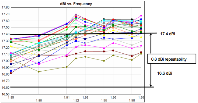
- The repeatability margin associated with a specified mean gain is that the value measured on all samples, at all times, on all calibrated test ranges shall not be more than 0.8 dB lower than the specified value.
Testing & Reporting
Gain values are typically determined by the gain by substitution method, or the gain by directivity / loss method. These methods are briefly described below. Both methods can be used to validate the gain specification, and the validation process described below is applicable to gain data generated by either method.
Depending on antenna design, reporting of gain is based on the average value measured on all relevant ports and over the specified subband frequency ranges. The antenna gain must be specified for each of the subbands included in the frequency range of the antenna.
For antennas with electrical tilt, gain must also be reported at low, mid, and high electrical downtilt settings. A gain over all tilts is also specified, and it is calculated using measurements over all the antenna downtilt values.
Gain measurements must be made carefully to assure accuracy. It can difficult to repeat a gain validation measurement precisely and the accuracy and repeatability of a gain measurement is determined by a number of factors. Accordingly manufacturers generally define a repeatability margin, typically set between 0.5 and 1.0 dB - this means that repeated measurements of gain must fall within this tolerance.
Testing Methods
Two methods of testing for antenna gain are generally accepted - Gain by Substitution, and Gain by Directivity/Loss. The latter will not be discussed in detail due to its complexity.
Gain by Substitution/Comparison
Gain by Substitution method, also called Gain by Comparison method, involves using a known gain reference antenna to compare the antenna under test with. The gain reference antenna is typically an absolute gain calibrated standard gain horn. Due to its simplicity and accuracy, Gain by substitution/comparison tends to be the most widely used and accepted, and forms the basis of IEC 60835-2-2 and ETSI EN 301 126-3-1.
The first step is to calibrate the system using the gain reference. Position the gain reference in its phase center and main beam direction and calibrate the system (zero reference). Calibrate for each individual polarization of interest since the transfer function of the range can be different in different polarizations.
Step two is to measure the antenna under test in its phase center and main beam direction.
The gain of the antenna under test is found by taking the measured values under step two and adding the known gain of the reference antenna which is typically found in a gain table delivered with the antenna.
Gain by Directivity/Loss Method
Gain (G) and directivity (D) are linked by the formula G = k x D, where the antenna effective factor k (0 ≤ k ≤ 1) corresponds to the overall losses of the antenna. Accordingly antenna gain can be calculated by the following formula, where a represents antenna losses comprising of all ohmic and dielectric losses between the input connector and the outer surface of the radome and the loss due to the impedance mismatch.
G[dB] = D[dB] - aantenna [dB]
With a spherical near field measurement system, the whole surface of a base station antenna can almost be measured without any disturbance through the measurement system themselves. The directivity (D) cannot be measured directly, but calculated from the normalized power pattern or full 3D pattern measurement.
References
- NGMN, "Recommendations on Base Station Antenna Standards", NGMN Alliance, N-P-BASTA v11.1, Mar. 2019.
- FEKO, Product Applications - Antenna Analysis, [Online], Available: https://www.feko.info/applications/antenna-analysis